
What is Backlight
2025/11/24
Why a Backlight Is Needed
l Liquid crystal material does not emit light; it can only modulate the intensity of incoming polarized light. Without a backlight the panel would remain completely dark.
How the Backlight Works
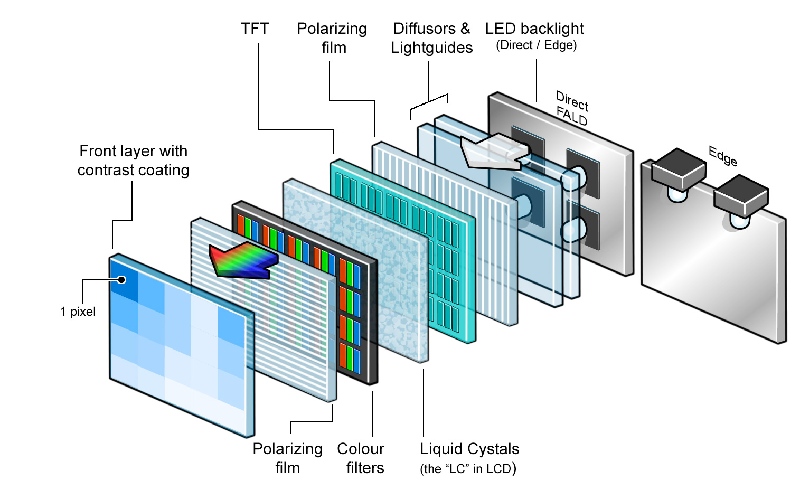
1.Light-source layer – LEDs (white LEDs are most common; RGB?LED arrays are also used) generate the initial radiation. LEDs offer high luminous efficacy, low power consumption and long lifetime. Mini-LED packs thousands to tens of thousands of tiny LEDs into the same area, enabling local dimming.
2.Optical-gel / scattering layer – A transparent gel or particle-filled scattering film homogenises the point -source beams and prevents hot spots from being projected directly onto the light-guide plate.
3.Light-guide plate (LGP) – Made of acrylic or optical glass with micro-holes or micro-prisms etched inside. By total internal reflection the light travels laterally across the plate and is gradually coupled out through the micro?structures, providing uniform global illumination. Hole size and density determine uniformity and out-coupling efficiency.
4.Diffuser – A milky or semi-transparent plastic film that further smooths the light distribution and eliminates local brightness variations caused by non-uniform micro-holes.
5.Brightness-enhancement film (BEF) – One or two layer micro-prism films that redirect scattered light forward, raising overall panel brightness by roughly 30-50%. The prism angles are designed to match the viewing angle of the display.
6.Polarizer sheets (front & rear) – Linear (or circular) polarizers. The front polarizer converts unpolarized light into linearly polarized light; the rear polarizer works together with the liquid-crystal layer so that the transmitted intensity varies with the orientation of the LC molecules, thereby forming the image.
7.TFT-driven liquid-crystal layer – An array of thin-film transistors (TFTs) supplies voltage to each pixel, controlling the rotation angle of the LC molecules and thus the amount of light that passes the rear polarizer. Different LC alignment modes (IPS, VA, TN, etc.) give different viewing-angle and contrast characteristics.
8.Protection / encapsulation layer – A glass or plastic sheet outside the polarizers that protects the panel from scratches, contamination and provides mechanical strength (e.g., Gorilla Glass, reinforced plastic).
Complete Structural Table (English)
|
Level |
Components |
Function |
Typical Implementation |
|
1. Light-source layer |
?LED array (white-LED dominant, RGB-LED optional) Edge-LED, Mini-LED, Micro-LED variants |
Generates the primary light. LEDs are high-efficiency, low-power, long-life. Mini-LED packs thousands-to-tens-of-thousands of micro-LEDs for local dimming. |
Direct-backlight (LEDs evenly placed behind the panel) or edge-lighting (LEDs on the four sides). |
|
2. Optical-gel / scattering layer |
Transparent optical gel, particle-based scattering agents |
Homogenises the intense point beams, preventing hot spots on the light-guide plate. |
High-refractive-index gel or particle-filled scattering film. |
|
3. Light-guide plate (LGP) |
Acrylic or optical-glass substrate with etched micro-holes / micro-prisms |
Uses total internal reflection to guide light laterally; micro-structures gradually couple light out, achieving global illumination. Hole size & density dictate uniformity and out-coupling efficiency. |
Typical hole diameters 10-30μm; density adjusted according to panel thickness and brightness requirements. |
|
4. Diffuser |
Milky or semi-transparent plastic film |
Further smooths light intensity distribution, eliminating local brightness differences caused by uneven micro-holes. |
Multi-layer micro-structure or particle-dispersed diffuser. |
|
5. Brightness-enhancement film (BEF) |
Micro-prism optical films (single- or double-direction) |
Refocuses scattered light forward, raising overall panel brightness by 30-50%. |
Usually 1-2 prism layers; prism angles matched to display viewing angle. |
|
6. Polarizer sheets (front & rear) |
Linear or circular polarizers |
Front polarizer converts unpolarized light to linear polarization; rear polarizer works with the LC layer so that transmitted intensity varies with LC molecule orientation, creating the image. |
Front polarizer placed at the outermost side of the backlight; rear polarizer directly contacts the LC layer. |
|
7. TFT-driven LC layer |
TFT array + liquid-crystal material |
TFTs address each pixel, supplying voltage that rotates LC molecules, modulating light passing through the rear polarizer to render grayscale/color per pixel. |
IPS, VA, TN, etc., each giving different viewing-angle and contrast traits. |
|
8. Protection / encapsulation layer |
Protective glass or plastic outside the polarizers |
Shields the panel from scratches, contamination and adds mechanical rigidity. |
Gorilla Glass, reinforced polymers, etc. |
Key Technical Points
Local Dimming (Mini-LED)
l Thousands-to-tens-of-thousands of micro-LEDs are grouped into “zones.” Each zone can be dimmed independently based on scene brightness, turning off LEDs in dark areas and keeping them bright in highlighted regions, which yields higher contrast and deeper blacks.
l Challenges: high-speed driver ICs, fine zone partitioning, and complex algorithms that synchronize dimming with video content.
Balancing Luminous Efficiency & Uniformity
l LGP micro-hole design: larger holes and higher density improve out-coupling efficiency but may degrade uniformity. Designers trade off cd/m2 (luminance) against Δ% (uniformity).
l Multi-layer diffusers: stacking diffusers with different scattering angles can retain high brightness while improving uniformity.
Color-Gamut Enhancement
l Quantum-dot enhancement film (QDEF): a quantum-dot layer on top of the LED backlight converts blue light into highly pure red and green, dramatically expanding BT.2020 and DCI-P3 coverage.
l RGB?LED backlight: directly uses red, green, blue LEDs for precise colour control, though it raises cost and driver complexity.
Power-Management (PWM vs. DC Dimming)
l PWM: adjusts duty cycle; power scales linearly with brightness but can introduce high-frequency flicker.
l DC dimming: varies LED current; reduces flicker but offers less power saving at low brightness. Commercial products often combine both—PWM for high-brightness levels, DC for low-brightness operation.
Thin-Form-Factor Trends
l Edge-LED + ultra-thin LGP: LEDs placed on the panel edges together with high-refractive-index light guides can shrink total thickness below 5mm, suitable for ultra-slim laptops and tablets.
l Mini-LED with thin substrates: maintains local-dimming benefits while using thinner base materials to further reduce panel depth.
Typical Product Stack (textual diagram)
[Outer protective glass / cover layer]
↓
[Front polarizer] → generates linearly polarized light
↓
[Liquid-crystal layer + TFT driver] → voltage controls LC rotation → modulates transmitted light
↓
[Rear polarizer] → works with LC to produce image contrast
↓
[Brightness enhancement film (BEF)] → concentrates light, raises brightness
↓
[Diffuser] → smooths intensity distribution
↓
[Light guide plate (LGP)] → spreads light uniformly across the panel
↓
[Optical gel / scattering layer] → homogenises point source LED light
↓
[LED array] (or Mini-LED / Edge-LED)
Development Outlook
l Mini-LED / Micro-LED: higher peak luminance, finer local-dimming granularity; expanding into 4K/8K large-size TVs.
l Quantum-dot backlights: combined with Mini-LED to push BT.2020 colour gamut and meet HDR10+, Dolby Vision, etc.
l Ultra-thin Edge-LED + high-index LGP: panels thinner than 5-mm, enabling foldable/rollable displays.
l Low-frequency PWM / hybrid DC dimming: improves eye-comfort while maintaining energy efficiency, especially valuable for mobile devices.
Through the coordinated stack of components and the key technologies above, TFT-LCD panels can deliver ever-greater brightness, contrast, colour gamut and power efficiency while retaining the cost advantages that make them dominant across smartphones, tablets, monitors, TVs and professional displays.